
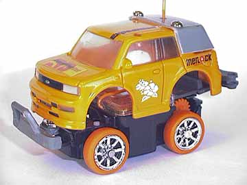
fig. 63 - rollover image to see rear view.
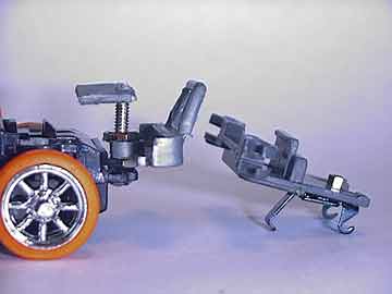
fig. 64 - rollover image to see chassis.
 27.
4x4 Body Lift
27.
4x4 Body Lift
This intermediate modification securely lifts your Bit body to give the appearance of a monster truck. What is required are small/micro screws and nuts, the BitChar-G Body adapter and Guide Roller (a.k.a. Bumper) for the Bit Racer. These parts come with most body sets, or Bit Racer Machine Sets.
First start by mounting the Guide Roller onto the Heat Sink of your BitChar-G. To do this, you must drill a hole through both your Guide Roller and your Heat Sink. If you choose to secure through a preexisting hole in your Heat Sink, it is only necessary to drill a hole into your Guide Roller. Take great care to measure your placement of the Guide Roller onto the Heat Sink, because placing the roller too far forward over the Heat Sinks leading (forward) edge, will make snapping the Heat Sink in very difficult. Although there is leeway for your placement, I suggest placing the Guide Roller almost flush with the Heat Sink's leading edge (the side with two hooks). You may also want to sand down the sides of the Guide Roller that mount over the Heat Sink to conform to the Heat Sink's width (this is optional).
Next, drill a small hole into your front tab which normally secures the body. keep the hole small to ensure the integrity of the tab. Insert a machine screw (preferably 2.56mm or smaller) through the bottom upward. secure in place with a nut. Now drill a hole into the BitChar-G body adapter tab, and screw into the preferred height for your body lift. (FYI: the BitChar-G Body Adapter for the Bit Racer is the part that secures a BitChar-G body to the front of the Bit Racer, if you choose not to use the guide roller. If your are not sure which it is, it is the other piece that comes with the Guide Roller, that looks like a small body tab.)
Note: I chose not to use a body tab to mount the front, and instead cut a custom piece of plastic to secure the front end. I also chose to add a custom bumper in the front (from a toy car), which is secured with another nut. See fig. 64
28. 4 Point 4x4 Monster Truck Suspension
(and Monster Truck Tires).
This rather complicated mod provides complete four point monster truck independent suspension and a lift for for your body. Although largely aesthetic, if combined with the spring suspension mod, you can also achieve independent front chassis suspension. be advised this mod pools a motley of parts that may not be easy to obtain.
The front suspension uses the axles and nuts from a BMX finger bike,
micro springs, 2.56mm machine screws, and spacers
from anything you can create it from. Begin by removing your stabius and
drilling small holes into both ends. Reinsert upside down and screw both
axles from the BMX bike into the holes (this acts as dual shafts for shocks).
Place your Bit body over the BMX axles and drill holes in the corresponding
area on the hood. Slide micro springs over the axles, then slide the spacers
on above the springs. Place the body on, allowing the axles to pass thru
the holes, then secure using small nuts.
NOTE: The length of the spacers depends on the length of your axle
(shaft) and the desired height.
The rear suspension uses the same pieces with the addition of a Bit Racer
Guide Roller. Start by attaching the guide roller onto your heatsink.
I chose to drill a hole thru both pieces and secured with a micro machine
screw and nut. Next, place the body over the guide roller, and drill holes
into the body where the ends of the Guide Roller align with the body.
Assemble the rear shocks by screwing a nut onto one end of the BMX axle.
Slide a spacer* onto the axle, followed by the spring, then another spacer.
Now insert the semi-assembled shock into either hole (in the body) from
beneath, and secure with another nut on top. Do this for both sides. Now
just snap the bottom spacers of the shocks into each end of the guide
roller!

fig. 65
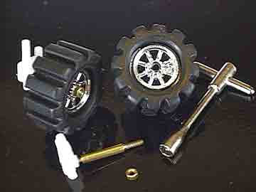
fig. 66 - Rollover to see various sized tires
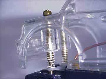
fig. 67 - Rollover to see compression

fig. 68 - Rollover to see compression
NOTE: The length of the spacers depends on the length of your axle (shaft) and the desired height. *Bottom spacers diameter must be able to snap into the guide Roller ends snugly. You can drill a hole thru the circular rolling pins included with the Guide Rollers for use as the bottom spacers.
Although this mod focuses on four point suspension, I will briefly cover
monster tires as well. Several diameters may be used. Rollover the front
axle assembly image in fig. 66 to see compatible tires. The smallest
tire is hard to find, but the middle tire comes from a stomper which is
readily available in any Walgreens or ToysRus. Monster tires require longer
axles in both the front and the back in order to allow clearance from
the chassis. replace your front axle pins with another BMX axle. Just
screw into place, then slide your rim and tire onto the other end of the
axle. Your rim should not be able to slide all the way into the steering
knuckle, because of the way the BMX axle is designed, but if it does,
you will require spacers to keep the rims at a distance from the body.
Use a nut over the rim to secure. (see fig. 66) Modifying the rear
axle is covered in mods 3 & 21,
but please keep in mind that this mod requires a longer axle.
NOTE: Using monster sized rubber tires with a wide surface area strains
steering. You will find steering will often not respond unless the car
is in forward or reverse motion. Using hard plastic tires like the largest
tire in the rollover image in fig. 66 solves this issue. Combining
with a 2.4v mod will also solve this issue.
Because this mod provides ample space beneath the body, it can be complimented with additional mods, like dual cell turbo, or an LED or Fiber Optic light mod. However these additional mods are covered elsewhere on the site, and are not included here, to provide the reader with an unobstructed view of the mod. Hence the clear body.
29. Increasing Range (III)
(Removing Cripple Capacitor from Circuit Board)
This is a mod from Gamecubeman for increasing range on the car itself! It seems as though Tomy is developing more ways to inhibit the range of the Bits to allow for simultaneous multiple-car indoor usage. Thier newest attempt is to place a micro capacitor on the Printed Circuit Board (PCB) itself. This capacitor appears in the Supra, and presumably on all the other cars to follow.
To begin, remove the clear PCB cover, and with the car facing you, look closely at the edge of the board closest to you. In fig. 69, the capacitor is indicated with the white arrow, and the yellow X's indicate the contact points on the PCB that it bridges.
To remove, clasp the capacitor carefully with tweezers and touch the soldered ends with a solder gun to melt off the solder and release it. The capacitor looks as though it was added after the circuit board was manufactured, so the solder may appear lumpy or messy, and this may overflow when unsoldering. Be careful not to get solder on any other part of the circuit board, to avoid shorts. You can use a solder braid to help remove the loose solder from the board.
Fig. 70 shows a circuit board of an older BitChar-G that doesn't have the capacitor. Caveat: People have posted mixed results from this mod, with increases in range varying from just a half foot gain to a maximum range of twenty feet!
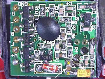
fig. 69
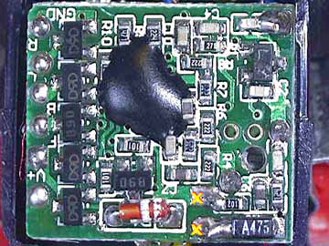
fig. 70