

fig. 56
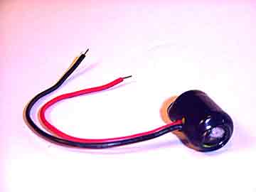
fig. 57

 25. 2.4v (dual cell) Bit Turbo
This is a variation of the now infamous mod created by Bit hobbyist Prabbit. Unlike most 2.4v Dual Cell Bits that center the second cell within the body shell to reduce whelies, this mod places the additional cell outside the body in the rear of the car. The wheelie effect in solved by using a wheelie bar.
This incredible mod boosts the speed of your Bit comparably to that of a Digi-Q, possibly faster, by doubling the voltage to the motor. This mod requires 2 identical rechargeable cells and some soldering. Either a pair of NiCd or NiMH can be used. The cells are wired in series, not parallel. The positive chassis contact tab (used for charging) should connect to the negative end of the second cell. The positive end of the second cell must connect with the negative end of the first cell. The positive end of the first cell connects normally to the negative contact tab of the cars chassis. Refer to the diagram of how to wire in series to better understand where we intend to connect the wiring to and from. (see fig. 56)
Start by creating a modular second cell. Solder two 24 gauge (or smaller) wires to both ends of the cell. Preferably red for positive and black for negative. Shrinkwrap the cell to secure the wiring. (see fig. 57) Your car must have the Tailskid Guide Bumper mod or similar location to mount the additional cell. Mount the modular cell onto the Tailskid Guide Bumper and run the wires through the tailskid bumper and under the motor well. remove your rear axle then run the wires up through the small hole "before" the rear axle shaft. (see fig.58) The wires will run up and out through the axle shaft. Leave the wires dangling for a moment and open up your clear PCB (circuit board) cover.
Next, run the wires to the original battery of your Bit thru the same small openings that the wires to the motor run out from. Be sure to adjust the wires in such a way that they do not impede free movement of the axle. The next step is to decide how you wish to connect the modular cell to the original cell. You can either solder to ensure a secure connection, or secure without soldering to facilitate easy removal or reconversion to a single cell Bit. I have chosen to solder my connections.
Connect the (red) positive wire from the second cell to the negative end of the first cell. Then connect the (black) negative wire from the second cell to the positive terminal contact tab of your Bit chassis. The negative end of your first cell and your chassis's positive contact tab must not be allowed to make contact. This can be done by inserting a rubber insulator. In this case, I have chosen to use a clear adhesive rubber foot for the job. (see fig. 59) Alternatively, you can tape over the negative end of the first cell, completely covering the contact area and the connection of the red wire from the second cell.
Note: I have chosen to solder the black wire that leads from the negative end of the second cell to a copper strip. I then insert the copper strip snugly between the chassis's positive contact tab and the sidewall of the chassis.
Once the wires are connected in place, make sure to do a simple test to assure proper contact. This can be done by sending a signal to steer left or right. Arrange the path of the wiring to best accomodate the tight quarters beneath the PCB board. When using a larger diameter gauge wire, its thickness often obstructs the PCB from laying flat and doesn't allow the clear PCB cover to secure in place. Refer to fig. 60 to see the final layout of the wiring from the second cell to the first cell.
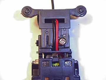
fig. 58
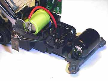
fig. 59
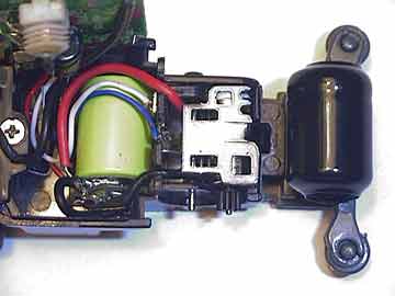
fig. 60
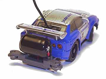
fig. 61
Your 2.4v Cell is now complete. I use a micro B 1.0 motor with my dual cell Bit because its boosted speed is comparable to a single cell Bit with a 2.6 motor, and it puts the otherwise unused motor to good use. I have tested my 3.8 motor in the dual cell Bit, but have been unable to achieve top speed on my kitchen floor because it isn't long enough to accomodate a full throttle sprint. Halfway into acceleration, I am required to release the forward button prematurely to allow the Bit roll about 24 inches to a complete stop, else I risk slamming it into the wall.
Note: Your controller CANNOT charge multiple cell configurations without modification. So in order to successfully complete this mod, you must also modify your controllers charger to allow direct charging (Thanks to B-Drift for this one), or create a stand-alone charger.
( Direct Charging for Multiple Cell Bits )
This mod converts your Bit controller/charger to be able to charge multiple cell turbo mod cars. The mod bypasses the controllers circuitry which normally regulates the charging voltage, allowing your Bit to receive a full 3V charge. Cars modified to higher than 2.4V may have to use the Stand-Alone Charger.
Start by opening up your controller. Unsolder or cut the wires leading from the circuit board to the charging base plate. Remove the ends attached to the circuit board. See the "X" marks in fig. 62. Resolder the wires to the corresponding terminals of the battery case. See the highlighted "circles" in fig. 62. Be sure to follow the color coding of the wires to ensure a proper connection. It is important to note that you will no longer be able to use the built-in timer, as you have bypassed it. Keep track of your charging time to avoid overcharging your cells. Charging time depends on the combined capacity of the cells used.
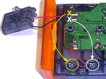
fig. 62