

fig. 9
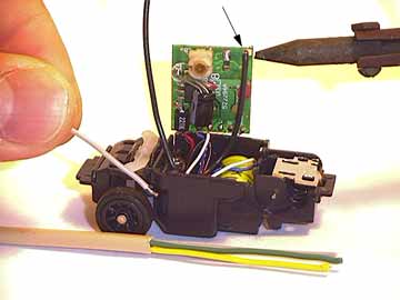
fig. 10


5. Car Antenna Upgrade
This mod replaces your stock antenna with a longer, and larger gauge solid copper antenna wire, and your choice of color. (See fig. 9) This mod improves reception, and looks great! You will need a soldering iron, solder, and copper wire of similar or slightly larger gauge than the stock antenna. Buy a 4-color pack of antenna wire in our online store.
Open up your bit and remove the clear IC cover. Lift the PCB board and turn it over. Unsolder the original grey antenna wire in the corner. Replace and resolder the new antenna wire of your choice. (See fig. 10) Take note of where the original solder was, and when resoldering, be careful not to have your new solder spill over and touch anything its not supposed to on the PCB board.
You can match the length of the original antenna or customize your own length. I believe a longer length improves reception, and my cars use a total length of 120mm.
Please note: "Bit Guru PRabbit" recommends a length of 50-70mm. He also suggests that you can also use Commercial Grade Cat-5 cabling, because it has a solid copper core, and more colors! There are 8 colors to choose from within the Cat-5 cabling.
* To improve reception even more, see Modification No. 6 (Increasing Controller Range).
(Removing Cripple Capacitor)
The first generation of BitChar-Gs had an excellent range of anywhere between 15'-20' feet. Subsequent productions of BitChar-G's, espcially the newer models have a much shorter range. This is because Tomy added a capacitor to cripple the contollers effective range to within just a few feet before your car begins to stutter. Although most are unsure why Tomy elected to do this, it is mostly likely a type of federal compliance in regards to laws governing frequencies. Another theory is that it accomodates playing with several of the same frequencies within the same room. For example, imagine trying to run the races at the malls and clubs in Japan, with all those users in one room. Anyone could sabotage a race simply by turning on thier controller 15 feet away. With the limited range, you could run several races within a few feet of each other.
Removing the cripple capacitor is simple. You must first determine whether your controller has one or not. To do this, open up your controller. Look for components L3 and R9 on your circuit board. If there is a soldered capacitor that connects them, then your range has been crippled. If you do not see one, flip the board over to make sure it isnt on the other side. The capacitor is brown, can be anywhere between 10-45 pf, and usually has the number printed on it. (See fig. 11).
To remove the capacitor, cut or unsolder off at the ends, L3 and R9. (See fig. 12) Your effective range should immediately improve several feet. To improve your reception even more, see Modification No. 5 (antenna replacement).
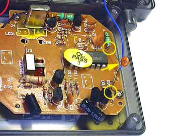
fig. 11
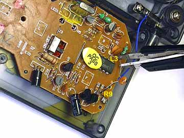
fig. 12
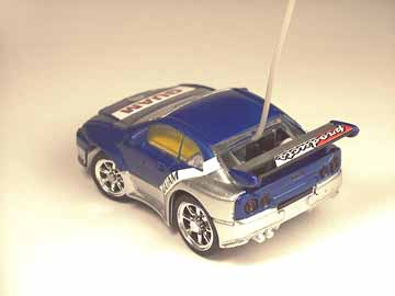
fig. 13
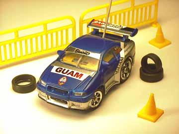
fig. 14
These are really just tips on painting your clear bodies. The "Team Guam Racing" body in fig. 13 & 14 uses the Guam flag as its theme as well as color scheme.
I recommend using Tamiya Polycarbonate & Lexan paints and sprays. I have not tested Testor brand paints. Its best to mask your car with masking tape, then trim the mask with an exacto knife to get your design lines just right. Dont use too much pressure, to avoid putting cuts in your bodies finish. If painting the bodies from the outside (easiest), remember to mask the head and tail lights first, then paint them from the underside afterward, to achieve a glassy look. To get a "clear" gloss, paint from beneath, as you would a 1/10th scale car. Masking from underneath is difficult, but yields a superior glossy finish! Be sure to do a final coat of clear gloss from underneath, because contact with the chassis will eventually scrape off the paint.
Decals can be found in the Tomy tune-up kit (the accessory set w/the spare battery). Or you can go to a slot car hobby shop and buy dry-transfer decals. These decals must be sprayed with gloss afterward. Or you can buy wet-transfer decals for model cars and airplanes, however these require a certain amount of finesse to apply!
Finally, if you're really brave, you can experiment with putty, sandpaper, and a dremel, to create your own wheelwell flares, grounds, air dams, etc... I have seen some pretty impressive putty mods on the net.
 8. Spring Suspension
This mod adds superior front spring suspension to your BitChar-G. This replaces, or can be used in addition to the purple, red or white accessory set sway bars. This mod requires a wire cutter, and small diameter micro springs that fit snugly around the vertical shaft of the front axle knuckle assembly. You can buy a pair of Tomy XP300 Micro Springs in our online store.
To start, Disassemble your front end. Remove your white steering knuckles. Customize your springs by cutting them to your preferred size. Slide them over the vertical shaft of the steering knuckle, and reassemble. (see fig. 15) To see how the springs slide onto the knuckles, click here. Its best to test the steering before reassembling completely, in case you need to adjust spring length.
Please note: I used the original Tomy springs at varying lengths for different cars. At stock length, they are approx 2-3mm longer than the shaft itself. At this length, suspension is too stiff, and tension affects steering adversely. Best results occur when cut to the length of the visibly exposed part of the shaft (where the spring goes) when the black cover is on. At this length, the car is springy, and the springs compress slightly on the cars own weight when set down. Cutting the springs shorter than that, lowers the front end while still having a springy suspension. However, this requires that you remove your sway bar, because the sway bar props up the front end, and defeats the lowering effect. (see fig. 16). Chassis height measured at the front body tab.
For great tips on how-to disassemble the the front end, visit ausmicro.com.
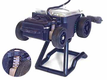
fig. 15
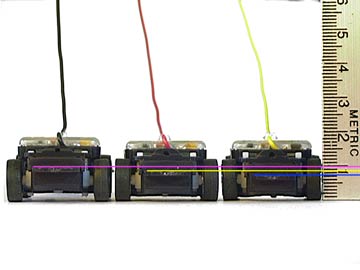
fig. 16 ( L-R: Optimum Spring Length, Shortened, None )