*This document was copied and updated with images from BitCal-B*
Make sure you read ALL the instructions at least once before even
heading out to the store. Then re-read them. A small goof can lead to a
LOT of extra heartache.
Parts List
In all possible cases I've included the Radio Shack Stock # for reference.
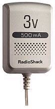
The first two parts make up the adapter that plugs into the wall:
3V 700mA Power Adapter (273-1756)
* Adaptaplug "N" 5.5mm OD x 2.5mm ID (273-1717) Note that
this comes free with purchase of the Power Adapter |
 |
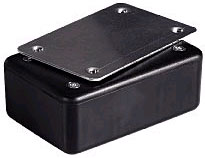
These are the parts that you have to put together:
| 3 x 2 x 1 in. Project Enclosure (270-1801)
|
 |
| |
|
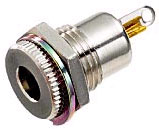
| Coaxial DC Power Jack 5.5mm OD x 2.5mm ID (274-1576A)
|
 |
| |
|
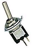
PC Board Toggle Switch (275-645A)
*Note that they have an identical switch not for PCs that also works and
has convenient holes in the contacts for soldering. |
 |
| |
|
5mm Blue LED 3.7V 20mA (276-316)
*
Note any LED with a rating of over 3V will work; pick a pretty one! |
? |
| |
|
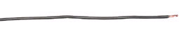
Hook-Up Wire (278-1221)
* Note that
if you already have wire, this is unecessary, but I recommend Solid
rather than Braided wire. |
 |
| |
|
Bit Char-G Power Platform (N/A)
* Note that any properly
spaced metal contacts will work, but if you have an extra controller because
you now have a 4-Channel one… |
|
Tools List
These are the tools you'll need for the project:
- Drill & Bits
- Soldering Iron & Electrical Solder
- X-Acto Saw or similar small cutting tool
- Small Crescent Wrench
- Small Phillips-Head Screwdriver
- Files or Sandpaper
- Two-Part Epoxy or other good glue
The Plan
 This plan shows where all the connections for the wiring go, and roughly how
they fit into the box.
This plan shows where all the connections for the wiring go, and roughly how
they fit into the box.
Step 1: Power Jack
The Power Jack is the only component that installs from the outside, and thus
needs to be dealt with first.
- With the top of the Project Box on, measure and mark the center of one of
the 2 x 1 in. sides; this will be the "bottom."
- On the opposite 2 x 1 in. side (top), mark and drill two holes for the LED
and Toggle Switch. Make sure that they are well clear of the lip of the Project
Enclosure lid when closed.
- Select a bit very slightly smaller than the OD of the threads of the Power
Jack and drill a hole in the box.
- Solder a red wire (approx. 3 in.) to the center contact (positive) of the
Jack.
- Solder two black wires: 3 in. and 1 ½ in. to the outside post (negative)
of the Jack.
- Screw the Power Jack into place and secure with its retaining nut.
Step 2: Solder Fest
Make sure that you have good soldering connections, melting your solder onto
the bits and not onto the tip of the iron. If you need help on soldering, ask
an old hand before starting. Better to make a good connection the first time
than have to go back and redo it!
- Solder the 3 in. red wire from the Power Jack onto one terminal of the Toggle
Switch.
- Solder 2 new pieces of red wire (both 1 ½ in.) to the other terminal of
the Toggle Switch.
- Solder the other end of one of the new pieces to the long (positive) terminal
of the LED; I strongly suggest cutting the lead down AFTER you've identified
and marked it.
- Solder the other piece to the positive contact of the Char-G Power Platform.
- Solder the 3in. black wire from the Power Jack to the short (negative) terminal
of the LED using the same technique as above.
- Solder the 1 ½ in. black wire from the Power Jack to the negative contact
of the Char-G Power Platform.
- All of the wiring should be connected and complete. Test it by plugging
in the Power Adapter; if the LED comes on, odds are it's good. Further test
it by charging a car. NOTE: the LED will be OFF while the car is charging.
Step 3: The Lid
To make a box that looks cool in addition to being functional, this is
one of the most important parts to get right, so go slow; maesure twice and cut
once!
- Measure and mark the center of the lid.
- Mark the openning for the Power Platform (18mm x 28mm).
- Drill pilot holes for your saw and cut out the openning.
- Mark and file out two 1mm x 5mm notches for the "grabber arms" of the platform.
- Test fit the platform and make minor adjustments by filing or sandpaper
till you're happy with the fit.
Step 4: Final Assembly
This is the easy part!
- Install the LED into the box, use a bit of epoxy around the lower lip of
the LED to keep it securely in place.
- Install the Toggle Switch into the box and secure it with its retaining
nut.
- Lightly score the Lid and Power Platform where they will touch (this makes
the glue hold better), and epoxy it into place.
- Wait far longer than recommended setting time of the epoxy. Nothing is worse
than getting too eager and having to redo the previous step.
- Use the screws provided to secure the Lid to the Project Enclosure.
- You're DONE!
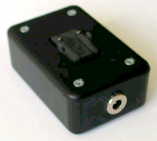
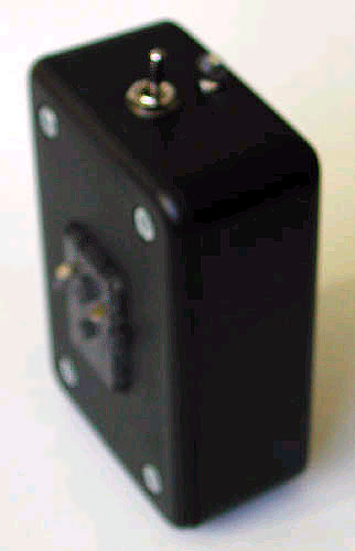
With minor variations in placing the LED and switch, it should look something
like this: